
Glass system
The glass rendering system in Fluid Flux 3.0 is built upon three interdependent systems integrated with the BP_FluxSurface actor. Each of these systems will be described in detail later in this chapter:
Masking
The geometry of the glass volume is captured in an SDF (Signed Distance Field), which is then used to cut holes in the surface mesh.Glass
TheBP_FluxGlassActorcan render any mesh as glass while sampling water height to apply advanced post-process effects like waterline refraction and absorption.- You can use multiple glass actors simultaneously.
- Note: Calculating water-related data is computationally intensive and processed per vertex. To ensure optimal results, glass meshes must have a high vertex density and use multiple layers of transparency.
Absorption
The volume mesh absorbs light within the underwater distance field, creating realistic underwater scenes enhanced by watercolor-inspired lighting effects. The effect is implemented inSurface.VolumeAbsorptionMaterial, which automatically applies the colors of the water based on the geometry inside the SDF attached to the surface. Clearing out this material disables the effect.
Example use cases of glass systems are presented on demonstration maps and can be found in the Demo/Maps folder:
FluxSectionMap– Only the glass system is used to render the borders of the simulation. The old fluid cross-section system was removed from the surface actor. This map uses a custom glass actorBP_FluxGlassSectionto achieve the effect of the water volume cut.FluxOceanMap– The simplest example of an SDF domain and a sphere of glass cutting a hole in the ocean.FluxCoastlineMap– Single SDF domain capturing the spline mesh tunnel and rendering glass combined with the coastline.FluxIslandMap– Advanced example presenting a mix of multiple types of SDF bodies and glass meshes (spline, Box, Sphere) and a simulation reacting on the glass mesh.UseCase_02_InverseTube– Inverted spline mesh glass and inverted SDF cut. Additionally, the configuration presents the top cap of the ground map used as a blocker for fluid inside the tube (see the ground map after selecting the Simulation Domain).
Examples
Example A – Basic configuration
- Prepare a map with water, and configure a surface actor (as in previous chapters). It’s important to make a complete configuration with a separate surface actor placed on the map.
- Drag and drop
BP_SDFVolumeDomainon the level and select the newly createdBP_SDFVolumeDomainon the map. - Adjust attributes of selected
BP_SDFVolumeDomain: location, resolution, and texel size to cover the area where the glass mesh should cut the hole. Make sure the water surface and glass effects are generated within the domain. - Find
BP_SDFVolumeDomain.TargetActorsand add an item that points to the water surface actor on your map (BP_FluxSurface). This step is important because from now on, the domain will send the generated SDF to this actor. This step forces the SDF system to send data to the Surface Actor and cut holes in it.
Example B – Adding a box/sphere-shaped glass container
- Drag and drop the Glass Actor
BP_FluxGlassBoxonto the level. - Select
BP_SDFVolumeDomain, find the SourceActors list. Add a new item to the list and set its reference to theBP_FluxGlassBoxyou just created on the map. The domain will read the shape data from this actor; you can add as many actors as you want. - Select
BP_SDFVolumeDomainand click CaptureDistanceFields. The button forces the signed distance field to be refreshed based on the current geometry.
Example C – Adding a glass tube (advanced)
- Add
BP_SDFOutlineon the map. This actor represents a canvas for spline actors. - Select
BP_SDFVolumeDomain, find the SourceActors list. Add a new item to the list and set its reference to theBP_SDFOutlineyou just created on the map. - Add
BP_FluxGlassSplineActorand set the MeshCrossectionSDF in it. It’s basically the description of the tube shape. - Select the
BP_SDFOutline - Adjust the
BP_SDFOutlinelocation, resolution, and world pixel size to overlap the spline actor area with the required precision. It’s good practice to start with the parameters toBP_SDFVolumeDomain, and you can later adjust the precision or size to get better/optimal results. - Select
BP_SDFOutlineand add spline actors to the CapturedActors list. This step is required to indicate to the system which spline actors should be used as data sources. - Select
BP_SDFVolumeDomainand click CaptureDistanceFields. The button forces the signed distance field to be refreshed based on the current geometry.
From now on, you should see holes in the surface of water. I’m aware that the current setup isn’t as straightforward as it should be, and I’m working on a much simpler solution that will bake SDFs directly from static meshes, eliminating the need for additional complex actors.
Masking surface
A Signed Distance Field (SDF) volume is a 3D representation where each point in space stores the shortest distance to the surface of a shape. The “signed” aspect means the distance is positive outside the shape and negative inside, allowing precise surface representation. Fluid Flux uses a signed distance field volume (BP_SDFVolumeDomain) to represent shapes that can cut holes in the water mesh surface. Sampling data from the SDF volume can determine if a point on the surface is inside or outside the shape.
Capturing shapes
Building an SDF volume requires capturing the distance to the surface of the scene geometry. The actors to capture are listed in the BP_SDFVolumeDomain.SourceActors array. These data sources can be generated differently depending on the type of geometry, and Fluid Flux supports a few basic types of SDF sources (implementing the BPI_SDFSource interface):
BP_SDFShape– The most straightforward mesh shape represents a box with round corners.BP_SDFOutline– Intermediate actor capturing data from Spline actor meshes that can capture many spline meshes simultaneously.BP_SDFProjection– capture scene geometry to heightmap and then convert to SDF (Experimental)BP_FluxGlassBox/BP_FluxGlassSphere– custom implementations of glass actors integrated withBP_SDFShape.
Sending data to actors
The BP_SDFVolumeDomain is the only container that generates and stores information about the signed distance field. That data needs to be sent to other actors for further use. The list of actors that should receive data from Domain is defined in BP_SDFVolumeDomain->TargetActors.
Example systems that use the SDF data:
BP_SDFPreview(implementsBPI_SDFRenderer) is a simple actor that can be used to debug the SDF on the plane mesh.BP_FluxSurface(attribute SignedDistanceFieldMask), the surface actor, uses that data to cut holes and volumes.
Exporting SDF to data asset
The system is designed to generate SDFs at runtime. However, an additional feature is the ability to save a baked SDF volume as a data asset (PDA_FluxSignedDistanceField). This enables the SDF to be stored statically on disk, bypassing the resource-intensive runtime generation process. The export method is similar to that used for other data assets in Fluid Flux.
- Create
PDA_FluxSignedDistanceFielddata asset. - Select
BP_SDFVolumeDomain - Right-click it and choose Scripted Actions →
SignedDistanceField->Export.
The exported PDA_FluxSignedDistanceField asset can be used directly in the Surface actor as BP_FluxSurface->SignedDistanceFieldMask. Remember to disable generation of the BP_SDFVolumeDomain by using the attribute AffectWorld=false or removing the Domain.
Limitations:
- SDF Domain Coverage – The SDF (Signed Distance Field) domain must cover the entire tunnel area, represented as a 3D texture. Stretching the SDF across a large scale can significantly increase memory usage. I intend to address this limitation by implementing virtual texturing in a future update.
- Spline Mesh to SDF Workflow – Baking spline meshes into the SDF is slow and involves multiple steps, which can be confusing for new users. I aim to streamline this process by transitioning the implementation to Niagara, making it more efficient and user-friendly.
- Surface hole precision – Holes cut in the surface using the SDF can occasionally look imprecise. While increasing the SDF resolution can address these issues, it may also lead to excessive memory consumption that exceeds practical budgets.
Glass rendering
The glass rendering system combines several materials that use advanced translucency rendering in Unreal Engine.
The system is based on BP_FluxGlassActor, which implements a few functionalities and attributes shared between numerous predefined types of glass actors that can be placed on a map:
BP_FluxGlassBoxBP_FluxGlassSphereBP_FluxGlassSectionBP_FluxGlassSplineActor
The glass is rendered as multiple instances of the same mesh, interpreted differently depending on the material used. Those material layers can be adjusted in glass actors:
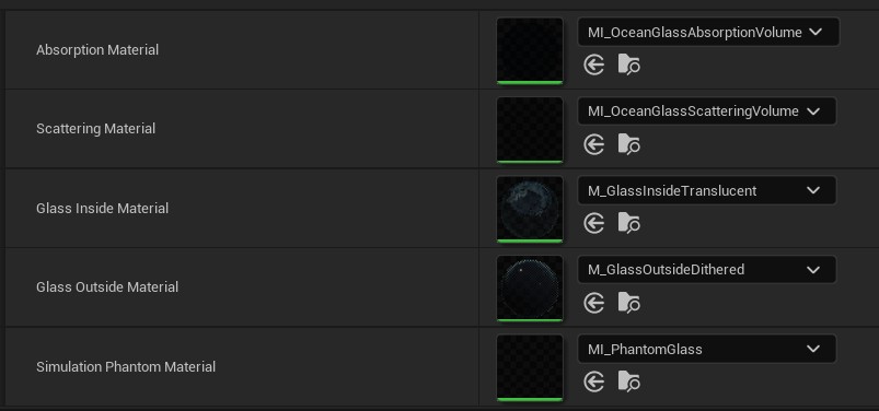
- Absorption/Scattering – is responsible for rendering the volume of water behind glass. The mesh utilizes data from the Fluid Flux surface to calculate depth and truncates the mesh in areas where water volume should not be displayed. It is rendered as two independent translucent passes, multiplicative absorption, and additive scattering. The scattering layer also supports the refraction effect of the waterline and water drops.
- Glass Inside – material used for rendering dirty glass and prebaked cube map refraction.
- Glass Outside – this layer renders the dithered glass material visible outside the tunnel. It utilizes dithered transparency, which causes some smearing but improves performance, fixes bugs related to invisible glass under single-layer water surfaces, and enhances translucency sorting. This mesh is also used to render soft shadows.
- Simulation Phantom – This mesh is used to exclude the area from the simulation ground map.